S1000D wiring modules provide a declarative means of capturing connectivity and hierarchical relationships of electrical or electronic equipment. With that said turning existing diagrams into S1000D diagrams is not a trivial exercise, at least not without good tools to automate a good deal of the processes involved. Many believe there are implicit open source resources that can do the job. Meaning the software is out there but its used for some other purpose. This is really sort of urban myth and the tools required to transform schematic graphical data into an S1000D wiring module are proprietary solutions; where there are not whole lot of players in this field. So one part of the need to get to a S1000D wiring capability or compliance is to transform existing diagrams, but what about once a system has been transformed how do you render from an S1000D wiring module?
The wiring modules do not provide very detailed graphical information, particularly relating to CGM. This is because the concept behind the S1000D wiring modules are to apply automation to the actual graphical rendering of the schematic from the connection information described in the modules. All component positions and wire routes are generated algorithmically. The wire paths are not described and usually machine intelligence can organize the components groupings better from the wiring module data than most human beings can!
The trick to rendering S1000D wiring modules lies in the understanding of mathematics called topology. This is inclusive of the wiring paths. Techniques that are available from sources like algorithmic recipes, some of which do have copy writes, are very limited and only provide a starting point. You're likely to have to resort to your own resourcefulness to solve the problems. Let's not forget the need to build up the schematic symbol library where legacy schematics have their own unique types and must be captured from original diagrams. In addition once those problems are solved there is the need to transform the data into a graphical open source format such as CGM or SVG.
There are other demands from an IEWD (Interactive Electronic Wiring Diagram) that need to be met. Most wire tracing solutions require the ability to separate circuits into powers, signals and grounds and high light and/or colorize them as such, as well as the ability to apply colors to wires at will. The wiring tool should provide lists of various component types, such as assemblies, jacks, plugs, relays, switches, circuit breakers, etc. There is a need to manage and apply inline "effectivity"(Lockheed term) or "applicability" within the diagram's coding! There must be an ability to associate auxiliary data such as images, pdfs, simulators and IETM exchanges. The tool must be able to navigate to other diagrams and continue a color trace. Also there is always the requirement to mark up the diagrams as well as print them. On top of those requirements described making the schematic colorful to distinguish component types is not part of the S1000D specifications and does require proprietary approaches to achieve.
Another issue that's not part of the S1000D specification are hot-spotting or high lighting rules. CGM provides a very well defined binary tag specification for hot-spotting but there are approaches within the specification that can allow for greater integrability to the S1000D wiring spec. Some of these approaches are component to component wire high lighting that the S1000D describes in the markup, coping with wiring harnesses and wire bundling (not a trivial task but can be encoded within CGM) to name a few.
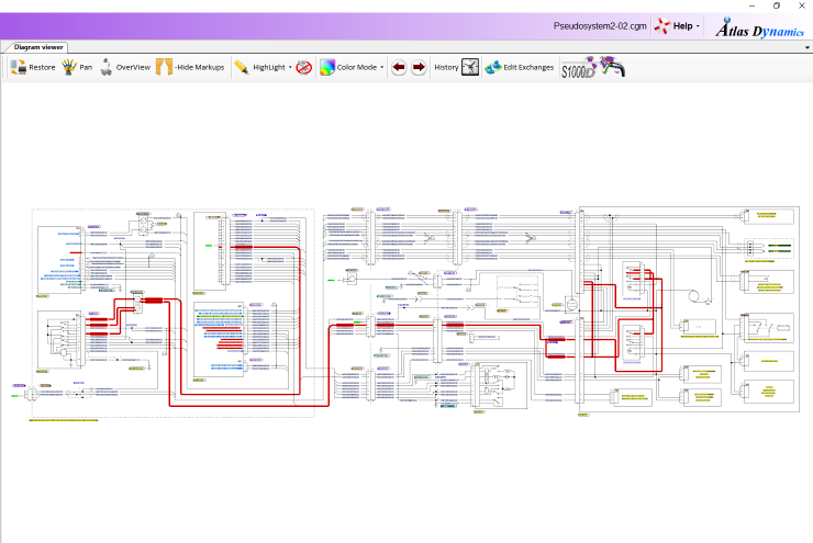
Conclusion: The computer generated schematic viewer is a complex piece of software and the development costs are very high, as implied earlier. Using COTS solutions are the most cost effective means to getting to a full S1000D wiring compliance solution today.
For further inquires:
Email: sales@atlasdynamics.com